RF
Avacend has an unparalleled expertise in providing complete network lifecycle support right from inception to operation.
In a cellular system, the coverage and quality of the network are almost inversely proportional, since when coverage increases it degrades the quality. Therefore, the main objective of the RF team is to achieve the maximum capacity for a network while providing acceptable quality of service to the users. The RF team ensure adequate network capacity as well as flexibility to be provided to the network to support the increases traffic requirements while being cost effective.
The RF part of any network deals with all the parameters related to radio waves which include frequency planning, location of antennas, antenna tilt & height besides continuous optimization of the network. The RF plan of a cellular system has two objectives viz. coverage and capacity. Coverage relates to the geographical footprint within the system that has sufficient RF signal strength to provide for a call / data session. Capacity relates to the capability of the system to sustain a given number of subscribers. Capacity and coverage are interrelated. To improve coverage, capacity has to be sacrificed, while to improve capacity, coverage will have to be sacrificed. The RF team has 2 major responsibilities to adhere to:-
- Network planning for new sites
- Maintenance and optimization of the present network
The network planning for new sites includes RF drive test results analysis, data from the OMC, frequency planning, post-optimization of sites, site location, antenna tilt, antenna height, link budget calculations, transmission planning, neighbouring cells definition and coverage area which are some of the aspects considered while planning a new site.

Besides the installation and annual maintenance cost of a BTS, one cannot randomly install a BTS without proper planning, because if a BTS is installed at a wrong location, it will not only degrade a network by creating interference to the nearby BTS sites but will also not generate the required revenue needed by the telecom operators. The location of BTS is properly decided after careful examination of the results obtained from drive test.
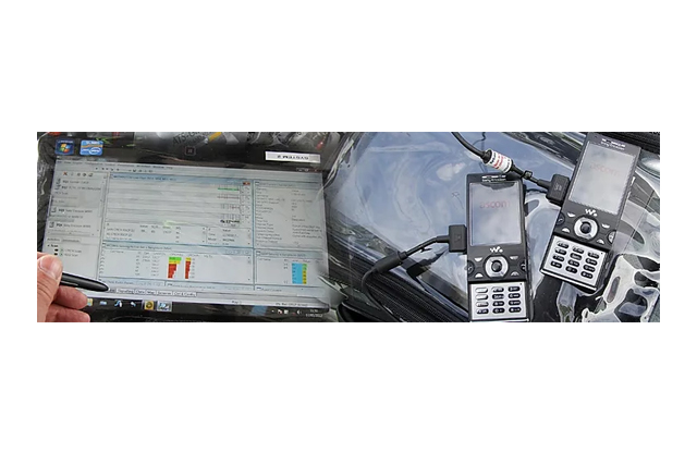
It is a method by which the coverage, capacity and Quality of Service (QoS) of a mobile radio network are measured and assessed. Our Drive Test engineers using a vehicle fitted with test engineering phones and measurement receivers interfaced with data logging RF drive test tools such as TEMS, NEMO, etc. to detect and record the RF parameters of network in a given geographical area. The data collected during the drive test would include parameters such as Signal intensity, Signal quality, Interference, Dropped calls, Blocked calls, Anomalous events, Call statistics, Service level statistics, Quality of Service (QoS) information, Handover information, Neighbouring cell information, GPS location coordinates, etc.


The log files from the RF Drive test are analyzed using RF tools such as Mapinfo producing results which allows us to analyze the radio network, simulate changes of network parameters, simulate changes of the network design, optimize the RF network, plan future roll-out phases and produces statistics on the selected results.
Link budged calculations is used to quantify a radio link’s performance in terms of all gains and losses associated with the RF signal travelling from transmitter to receiver through a medium. The link budget calculation is done in telecom to estimate the maximum allowable path loss which is further used to determine the base antenna heights.
Transmission planning plays an important part in mobile communication and involves connectivity of the BTS site with the BSC. The BTS site could be connected to the BSC directly through a neighbour site using either a microwave radio link or via fibre optic cable. The basic rule of a microwave radio link connectivity is that the both the sites should be in the perfect Line of sight (LOS). It is therefore important to understand and analyze the neighbours of the BTS site to understand how the connectivity would be planned and established.
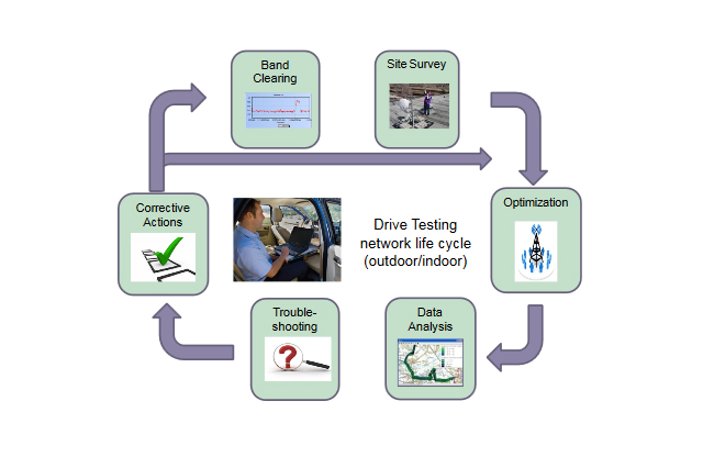
All deployed cellular networks, be it a 2G, 3G, LTE or 4G network, will have to be optimized after deployment to provide better coverage, throughput, lower latency and seamless integration as per the specifications. The optimization process contains several steps starting with drive testing where all performance parameters are tested and logged in the field after the network is active. This test should also include the different coverage & propagation scenarios along with their respective models (e.g., pedestrian, indoor, vehicular). The field data will then be used to calibrate the models for better network performance and coverage. Based on the collected data, RF planning engineers analyze the performance and maybe decide to add more BTSs, eNBs for coverage, mainly pico and femto cells, in the areas that show degraded power levels or data throughput. Femto cells will be used in LTE, as they will provide service for households and small businesses. Usually, the optimization process is an iterative one with no specific steps involved, rather than a set of consistent procedures that characterizes network performance and coverage in a certain area and actions are taken accordingly.
RF planning and optimization is carried out by our Engineers using post processing software & applications such as TEMS Investigation, Mapinfo Professional, Google Earth, Saltlake, Netnumen, etc.
